Bolu Viaducts and Tunnel
The November 12, 1999 earthquake caused substantial damage to one of the Bolu Viaducts and to the Bolu Tunnel, which was under construction at the time of the earthquake. The damaged viaduct, which was almost completed in November 1999, is labeled hereafter as Viaduct No. 2. Another Bolu Viaduct, which is referred to as Viaduct No. 1, was in an early stage of construction and did not display any visible sign of damage. The viaducts and tunnel are part of a 1.5 billion dollar project that aims at improving transportation in the mountainous terrain to the west of Bolu between Istanbul and Ankara. The estimated cost of the viaducts are 500 million dollar and that of the tunnel one billion dollar. When completed, this section of roadway will include a 3.2-km tunnel and two tall viaducts having a total length of approximately 6 km. Currently, a 3.5-km section of the viaduct is substantially complete, and approximately 2.3-km of the tunnel is excavated. It is worth pointing out that the viaducts and tunnel did perform well during the August 17, 1999, Kocaeli earthquake. At this time however, ground motions at the site were lower than those during the November 12, 1999 event.
Figure 1. Location of Bolu Viaducts and Tunnel.
Bolu Viaducts
As shown in Fig.1, there are 2 viaducts leading to the west portal of the Bolu tunnel. These viaducts are 2.5-km and 3.5-km simple-span structures supported on tall massive piers measuring as high as 45-m. As shown in Fig. 2, Viaduct No. 2 has the main characteristics listed in Table 1 and Figs. 3 and 4. The foundations of Viaduct No. 1 were still under construction at the time of the November 12, 1999 event.
Table 1. Main characteristics of the Bolu Viaduct No.2
------------------------------------------------------------------------------------
Length: 2313 meter
Width: 1 x 17.5 meter
Total number of piers 58 per carriage way
Maximum pier height: 49 meter
Maximum span: 39.6 meter
Pier foundations: 12-pile group with 1.8-m diameter friction pile
------------------------------------------------------------------------------------
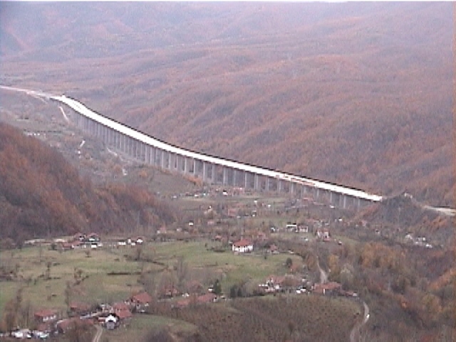
Figure 2. Overall view of the Bolu Viaduct No. 2 (November 18, 1999, 08:00:27).
Figure 3. Elevation of Piers of the Bolu Viaducts.
Figure 4. Elevation and top-view of pier and pile-group foundation of the Bolu Viaducts.
Passive energy damping devices have been incorporated into the viaduct structures to minimize damage caused by earthquake shaking. Figure 5 shows one of the devices manufactured by ALGA Corp. in Italy. The top portion of the device is an "energy dissipating unit (EDU) which uses "crescent moon" shaped yielding elements mounted between a central hub and an outer ring to provide two-dimensional energy dissipation in the horizontal plane over a 32-cm range of motion. The EDU is connected to the base by a pair of piston/dampers which allows the EDU to move with rate-controlled resistance in two dimensions.
Figure 6 shows a typical damper installation at the Bolu viaducts where the outer ring of the device is mounted to the end diaphragms of adjacent deck spans and the base is mounted to the bent cap. This installation essentially fixes the adjacent decks together, and thermal movements are accommodated by a piston/damper device supporting the energy dissipating unit. As shown in Fig. 7, relative movements between the bent cap and the deck elements mobilize both the piston/damper device and the energy dissipating unit in series
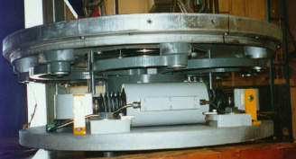
Figure 5. ALGA dampers similar to those installed into the Bolu viaducts.
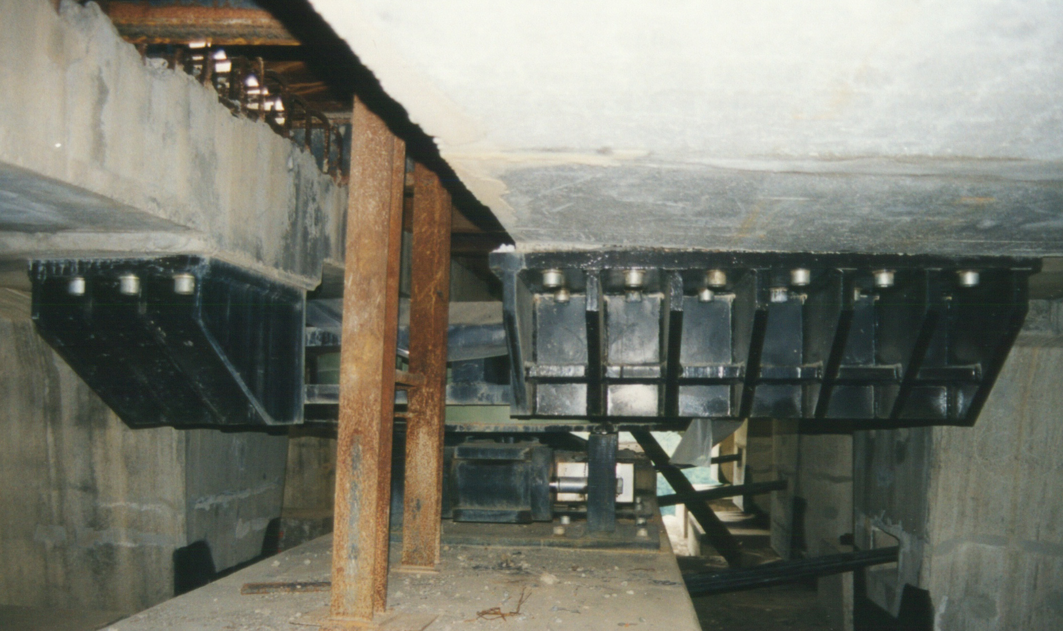
Figure 6. Damper installation atop bent cap between adjacent decks.
Figure 7. Location of damping, thermal and restrainer system along the Bolu Viaducts. R = longitudinal restrainer (60 cm slack), S= shock transmission unit for seismic movement, and P = piston for thermal movement..
Performance of the viaduct structures during the August 17, 1999 earthquake was fully satisfactory, Motions at the bearing pads of the deck relative to the bent cap measured approximately 8-cm longitudinally and 6-cm transversely. The dampers underwent 10-cm of deformation including 1-cm plastic deformation of the EDU. Miscellaneous damage at the viaduct included minor concrete spalling at an expansion joint where a temporary fixture had been installed, and toppling of several precast girders that were being stored in a pre-cast factory at Duzce.
During the November 12, 1999 earthquake, the viaduct structures did not perform as well as during the August 17, 1999 event. As shown in Figs 8 and 10, the viaduct construction facilities were damaged. Many precast girders that awaited their installation on Viaduct No. 1 toppled due to earthquake shaking. As shown in Figs 10 to 20, the viaduct deck moved in the longitudinal direction beyond its design limits. Many of the metal plates of the deck support fell down from the piers to the ground. Some sections of the deck were a few inches from failure. As shown in Fig. 17, the fault surface rupture intersected the viaduct axis at Pier 45 at a 20 - 30 degree angle. Pier 45 rotated as much as 12 degree due to the horizontal differential motion across the fault surface rupture. The strike-slip fault surface rupture generated a longitudinal permanent deformation in the viaduct deck as it intersected the viaduct at a low incidence angle. The viaduct has certainly been subjected to a combination of transient and permanent motions during the November 12, 1999 event. There is a definite need to study the response of the Bolu viaduct in detail before drawing conclusions on the causes of its poor performance.
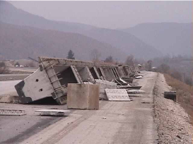
Figure 8. A large number of precast concrete beams that awaited installation in the Bolu Viaduct No. 1 toppled after the earthquake. Several precast girders were also reported to have toppled during the previous August 17, 1999, Kocaeli earthquake (November 17, 1999, 12:43:39, N 40.7814, E 31.3180).
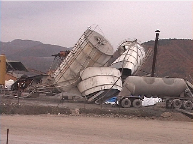
Figure 9. At the construction site of the Bolu Viaducts, silos fell down and were crushed (November 17, 1999, 12:52:48, N 40.7806, E 31.3314).
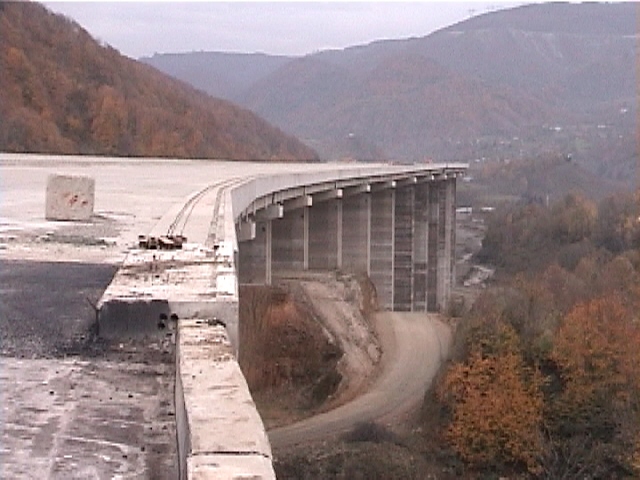
Figure 10. The western abutment of the Bolu Viaduct No. 2 (November 17, 1999, 12:58:08, N 40.7780, E 31.3517).
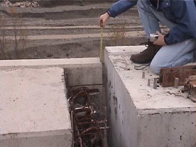
Figure 11. At the western abutment, the deck of the Bolu Viaduct No. 2 dropped 3 inches as its support failed (November 17, 1999, 12:59:43, N 40.7778 , E 31.3519).
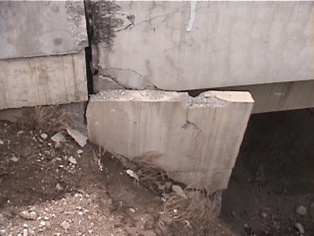
Figure 12. View of the failed deck support at the western abutment of the Bolu Viaduct No. 2 (November 17, 1999, 13:01:04, N 40.7776, E 31.3519).
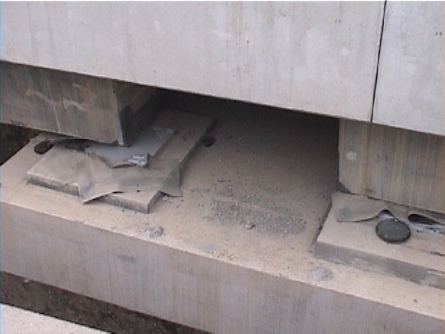
Figure 13. The deck of Bolu the Viaduct No. 2 moved permanently in the longitudinal and transverse directions (November 17, 1999, 13:09:27, N 40.7778, E 31.3520).
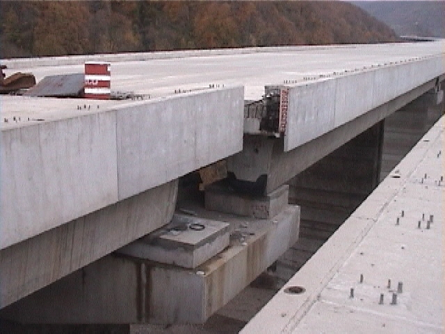
Figure 14. Some of the connections of the Bolu Viaduct No. 2 separated and the sections moved longitudinally and transversely (November 17, 1999, 13:19:39, N 40.7755, E 31.3555).
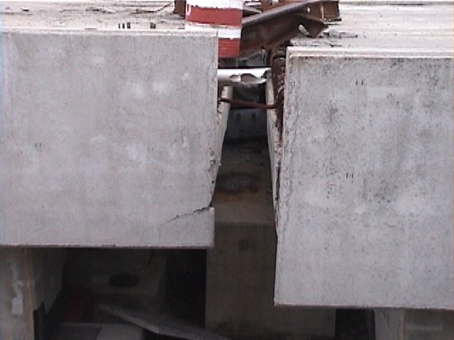
Figure 15. PVC pipes broke as the sections of the Bolu Viaduct deck were pulled apart (November 17, 1999, 13:19:00, N 40.7753, E 31.3556).
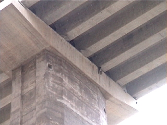
Figure 16. Some of the beams of the deck of the Bolu Viaduct moved longitudinally, and rested on top of the pier with only a few inches (November 17, 1999, 13:42:59, N 40.7717, E 31.3622).
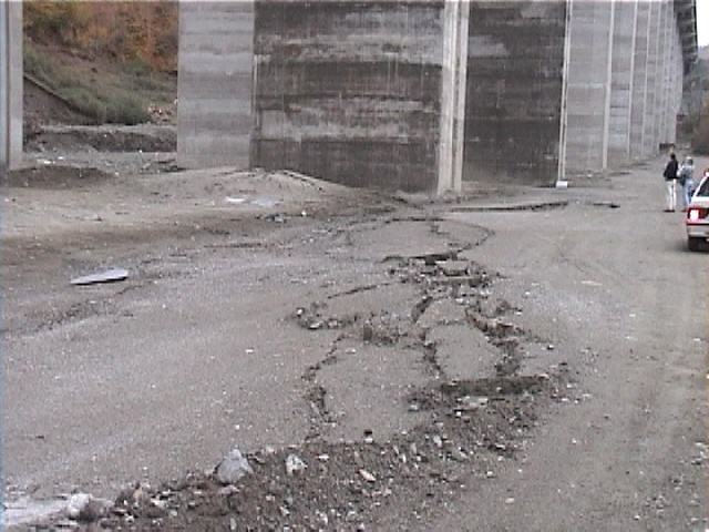
Figure 17. The fault surface rupture went through Pier 45 of the Bolu Viaduct No. 2 (November 17, 1999, 14:03:32, N 40.7698, E 31.3687).
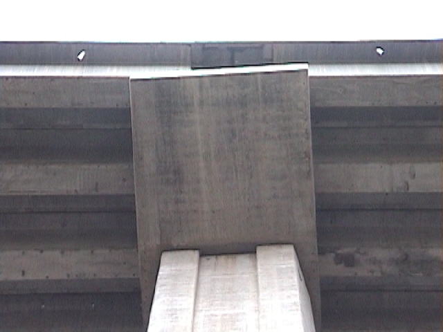
Figure 18. Pier 45 translated and rotated due to the fault surface rupture. The angle between the support and the deck was about 78 degrees, which implies a maximum pier rotation of 12 degrees (November 17, 1999, 14:01:29, N 40.7693, E 31.3686).
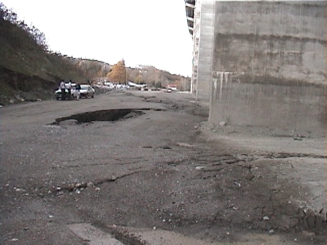
Figure 19. Pier 45 of the Bolu viaduct rotated and the embedding soil failed as it had been subjected to a huge vane shear test (November 18, 1999, 10:59:27, N 40.7683, E 31.3688).
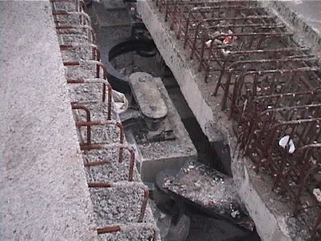
Figure 20. Failed damping/restrainer system at the eastern abutment of the Bolu Viaduct (November 18, 1999, 16:27:39, N 40.7664, E 31.3749).
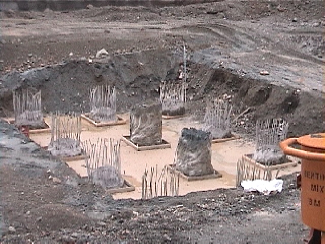
Figure 21. View of the pile foundation of Bolu Viaduct No. 1 under construction. The pier foundations of the Bolu Viaduct No. 2 are similar. They are made of twelve-pile groups. Each pile is 1.8 m in diameter (November 18, 1999, 16:10:38, N 40.7597, E 31.4167).
Bolu Tunnel
As shown in Figs. 22 to 24, the Bolu Tunnel is being excavated using conventional backhoes and earth moving equipment to have an excavated arch section 15-m tall by 16-m wide. Construction has been unusually challenging because the alignment crosses several minor faults parallel to the North Anatolian Fault. Shear zones have included 200-m to 300-m thick bands of highly plastic clay fault gouge sandwiched between a metamorphosed limestone and marble formation. Atterberg Limits performed on a grab sample of the gouge indicated a liquid limit of 100%, a plasticity index of 71%, and a natural water content of 22%.
The tunnel is being constructed using the New Austrian Tunneling Method (NATM) where continuous monitoring of primary liner convergence is performed and support elements are added until a stable system is established. Acceptance criteria for the primary tunnel liner call for a maximum total convergence of 200 mm at a rate not to exceed 2 mm/month. Because of the poor strength characteristics of the fault gouge, it has been difficult to achieve these acceptance criteria and closures of as much as 1 meter have been recorded. A variety of support systems including alternative liners and rock bolting have been attempted, and sections of the tunnel have had to be re-profiled. The current design calls for a primary liner consisting of an immediate application of a steel rib and a 30-45-cm layer of shotcrete containing steel fibers. This is followed within 30-m of the face by a 60-80-cm thick layer of high-strength B40 concrete to create a stiff hoop to restrict convergence. This system has been reported effective in meeting acceptance criteria. After convergence criteria are met, a final liner consisting of 40-70-cm thick layer of B30 unreinforced concrete is placed. The tunnel design does not explicitly consider accommodation of fault offset, but does incorporate additional steel mesh in the liner within areas of less than 50-m overburden (approximately 150-m of the portals) to minimize liner spalling at these critical locations during earthquake shaking.
The August 17, 1999 Koceali earthquake was reported to have had minimal impact on the Bolu tunnel. The closure rate of one monitoring station was reported to have temporarily increased to an accelerated rate for a period approximately 1 week, then became stable again. Additionally, several hairline cracks, which had previously been observed in the final lining, were being continuously monitored for additional movement and showed no movement due to the earthquake.
The November 12, 1999 earthquake caused the collapse of both tunnels 300 m from their eastern portal. At the time of the earthquake a 800 m section had been excavated, and a 300 section of unreinforced concrete lining had been completed. The collapse took place in clay gauge material in the unfinished section of the tunnel. The section was covered with shotcrete and had bolt anchor. The length of the collapsed section is not yet known.
Several mechanisms have been proposed for explaining the collapse of the tunnel. These mechanisms include strong ground motion, displacement across the gauge material, and landslide. It is still premature at this time to conclude on the cause of the tunnel collapse, and further investigation is needed.
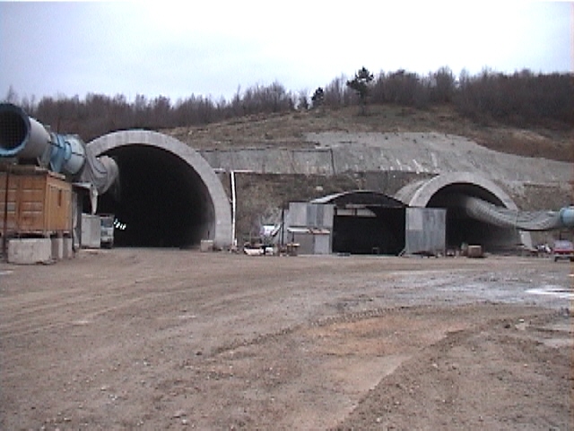
Figure 22. View of the eastern portal of the Bolu tunnel. The two tunnels collapsed 300 meters after the entrance. The collapse took place in unfinished sections that were covered with shotcrete and had bolt anchors. These sections had not yet concrete lining (November 18, 1999, 15:24:24, N 40.7307, E 31.4576).
Figure 23. Standard tunnel cross-section of the Bolu Tunnel.
Figure 24. Cross-section of a construction process used in the Bolu tunnel.