6.5 Gas Delivery System
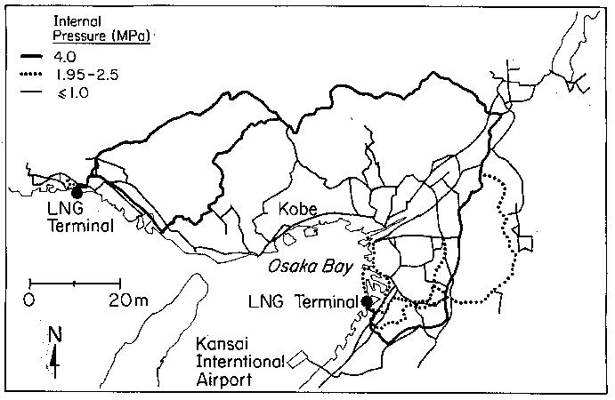
The gas delivery system for Kobe and surrounding communities is provided by the Osaka Gas Company. The company supplies gas in the Osaka Bay region to 5.7 million metered customers. A map of the Osaka gas pipelines with the highest internal pressures is shown in Figure 6.20. There are approximately 400 km of high pressure pipelines in the system, carrying pressure exceeding 1.95 MPa. There is a similar distance of medium pressure "A" lines with internal pressure between 0.3 and 1.0 MPa, which are also shown in Figure 6.20. Osaka Gas also operates medium pressure "B" lines at 0.1 to 0.3 MPa which are not shown in the figure. The low pressure distribution mains in the system operate at a pressure equivalent to about 20 cm of water column.
 Figure 6.20: Map of high pressure transmission and medium pressure trunk lines operated by the Osaka gas company.
The medium pressure A and B lines are composed predominantly of welded steel and ductile iron pipe with mechanical joints. In the Kobe area, the low pressure gas lines were composed predominantly of steel with threaded couplings. The total distance of transmission, trunk, and distribution mains in the Osaka Gas system is 49,430 km. There was no significantdamage reported at the LNG terminals, and no damage reported in the high pressure welded steel pipelines. Minor damage was reported in the medium pressure A lines, and the combined number of repairs in both medium pressure A and B lines was approximately 106.
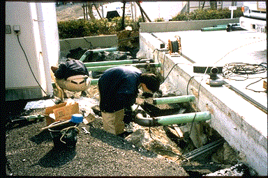
The principal source of damage was to threaded steel low pressure pipelines, where thousands of repairs are anticipated. Osaka Gas personnel noted that many of the repairs were at locations of permanent ground deformation caused by soil liquefaction and landslides, as illustrated in Figures 6.21 and 6.22. After the earthquake, the gas supply in the distribution system was shut off for 857,000 customers. Full restoration of service required 3 to 4 months.
 Figure 6.21: Repair of pipes separated by lateral spreading between a building and adjacent concrete slab near Nakahara Wharf, Port Island.
 Figure 6.22: Repaired pipes near Nakahara Wharf, Port Island. Prior to earthquake pipes followed a straight path between slabs.
 Figure 6.20: Map of high pressure transmission and medium pressure trunk lines operated by the Osaka gas company.
 Figure 6.21:
 Figure 6.22: