6.3 Water Supply
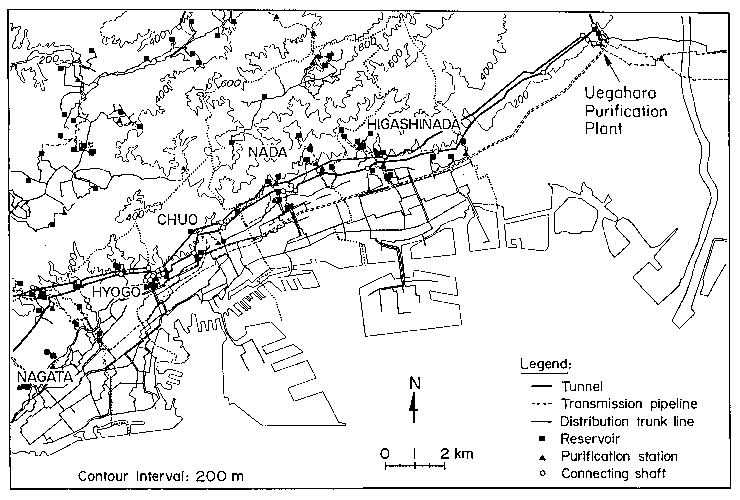
A map of the water distribution system operated by the Kobe Waterworks Bureau is shown in Figure 6.9. Approximately 75% of the water is taken from the Yodo River, and most of the remaining portion is obtained from a half dozen reservoirs throughout the area. Water from the Yodo River is treated at various purification plants and pumped to higher elevations through transmission tunnels and pipelines. There are 8 water purification plants and 57 km of transmission tunnels in the system. Minor to moderate damage was sustained at three purification plants. At the Uegahara Plant, ground deformation behind a retaining wall caused the joints to separate on three 1.5-m-diameter reinforced concrete pipelines which conveyed finished water from the plant. The Hanshin Water Authority purification plant, immediately adjacent to the Uegahara Plant, was affected by the Nigawa landslide which undermined the solids handling building.
 Figure 6.9: Map of Kobe Water Distribution System.
Water conveyed to elevations in the hills and mountains north of Kobe is stored in water distribution reservoirs which include cast-in-place concrete, precast concrete, and welded steel construction and have an average capacity of 4,200 m3. There are 119 distribution reservoir sites operated by the Kobe Waterworks Bureau, of which 86 provide water directly to Kobe City. Water is conveyed by gravity through pipelines to lower elevations. While only one reservoir, the Egeyama Reservoir, was damaged significantly as a result of the earthquake, a substantial amount of water was lost from the reservoirs because of broken and disengaged pipelines. Figure 6.10 is a graph showing the cumulative loss of reservoirs as a function of time after the earthquake. Between 6 and 24 hours after the earthquake, 86 reservoirs had emptied, leaving Kobe without critically needed water for fire fighting purposes.
 Figure 6.10: Bar graph of cumulative reservoir loss as a function of time after the earthquake.
There are 3,963 km of pipelines in the Kobe water supply and Table 6.1 summarizes the distances and relative percentages of each type of line. Approximately 86.3% of the system is composed of ductile iron pipelines, the great majority of which are equipped with standard mechanical joints that allow for relative rotation, but are not restrained against axial pullout. About 6% of the system is composed of ductile iron pipe with axially restrained mechanical joints. About 11% of the system is composed of cast iron and polyvinyl chloride (PVC). Welded steel pipelines account for 2.7% of the system, and are used for high pressure trunk and transmission lines. The steel pipelines are constructed with full penetration butt welds, similar to gas and liquid fuel lines, to provide for earthquake resistant strength and ductility.

Table 6.1: Summary of lengths and relative percentages of different pipelines in the Kobe Water Supply.
As of mid-February, 1995, there had been 778 repairs to distribution mains, and between one and two thousand were anticipated. There had been 3,084 instances of damage to services lines in public roads and 21,458 instances of similar damage on private property. Statistics compiled for a sample of 328 main repairs as of mid-February indicate that 41.5% of the repairs were because of pullout and ramming of pipeline joints, 16.2% associated with broken piping, 21% related to damaged hydrants and air valves, and 21.3% attributed to other causes.
Discussions with waterworks personnel indicate that pipeline damage in many instances was caused by permanent ground deformation related to liquefaction, landslides, and settlement of fill. The large percentage of repairs associated with pullout and ramming of joints implies a degree of axial deformation that the standard mechanical joints were not adequately designed to resist.
Until further investigations it is not possible to evaluate how specific patterns of permanent and transient ground motions influenced the integrity of the system. Nevertheless, it is possible to provide some general observations. Waterworks personnel have noted that bridge crossings of pipelines were especially vulnerable because of differential soil and bridge structure movements at abutments and deformations elsewhere along structural spans. Major trunk lines were damaged at the Port and Rokko Island Bridges. Furthermore, repairs at ductile iron pipelines with axially restrained mechanical joints appear to be low. There were no repairs to such pipelines on Rokko Island. In contrast, there were many repairs in ductile iron pipelines with conventional mechanical joints on Port Island. Figure 6.11 shows damage to a 700-mm-diameter welded steel trunk line on Port Island. This pipeline was the major trunk line providing all potable water to Port Island. It failed at a welded joint in an area of lateral spread at the north side of the island.
 Figure 6.11: Weld rupture of 700-mm-diameter steel water trunk main on Port Island.
 Figure 6.9: Map of Kobe Water Distribution System.
 Figure 6.10:
 Figure 6.11: