6.4 Sewage Treatment Facilities
There are eight sewage treatment plants for Kobe City, five of which were functioning after the earthquake. Two additional plants were returned to service within one week after the earthquake. Major damage was sustained at the Higashinada Plant, which is located just north of the Kansai Electric Higashinada Power Station (Figure 3.1). The design capacity of the Higashinada Plant was about 225,000 m3 of raw sewage per day. The oldest portions of the plant are 33 years old. Construction of the plant was started in 1962 shortly after the placement of fill for Uozaki Hama-cho was completed. It is anticipated that the plant will be closed for over a year until repairs are made.
Figure 6.12 is a map of the Higashinada Plant, and soil profiles for the borings shown on the map are presented in Figure 6.13. There was severe liquefaction-induced damage at the plant. Maximum lateral movement of the seawall north of the canal was approximately 1 m. Maximum lateral movement of the seawall south of the canal was roughly 2 m. Lateral displacement and settlement ruptured the inverted siphon at the plant (Figure 6.14) and caused separation of the main sewage treatment conduit through which raw sewage was conveyed (Figure 6.15). Because of the loss of the siphon, sewage was being dumped directly into the canal, which was screened by a temporary cofferdam at its eastern and western ends to create a temporary basin for primary sedimentation.
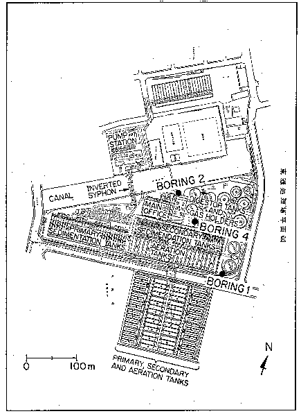 Figure 6.12: Map of Higashinada Sewage Treatment Plant.
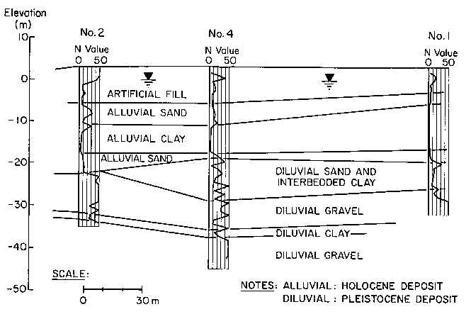 Figure 6.13: Soil profile at Higashinada Sewage Treatment Plant.
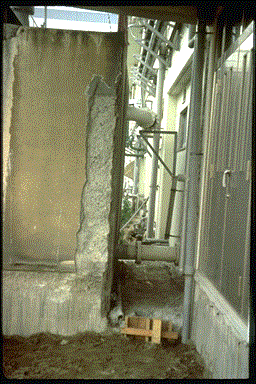 Figure 6.14: Severe lateral displacement at the inverted siphon of the plant. The pressurized pipeline siphon carried all sewage treated by the plant.
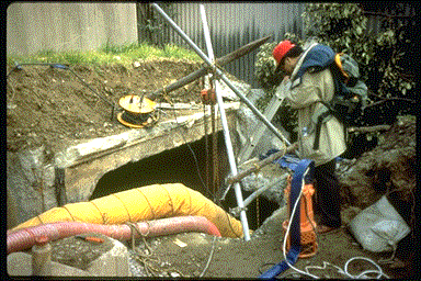 Figure 6.15: Rupture of the main sewage treatment conduit caused by lateral spreading and settlement.
Lateral deformation caused severe damage to underground structures and facilities founded on spread footings (Figure 6.16). Differential settlement of approximately 600 mm of soil relative to the pile supported sand filter building was observed (see Figure 6.17); and there was cracking and spalling at the tops of reinforced concrete piles which support this structure. Elsewhere, at the digester tanks closest to the canal, cracking at the tops of reinforced concrete piles was visible at several pits excavated to inspect the foundations.
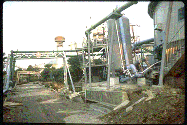 Figure 6.16: Plant facility damage due to lateral ground deformation and settlement.
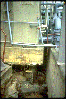 Figure 6.17: Differential settlement of soil relative to pile-supported structure containing sand filters.
The primary and secondary sedimentation and aeration tanks closest to the canal were supported on reinforced concrete piles. The primary sedimentation tank was 8 m deep so that the lengths of piles in the liquefied fill were relatively small. Very little damage was observed in this tank. The secondary sedimentation and aeration tanks were approximately 4 m deep, and consequently there were 4 m of additional pile length subject to liquefaction and lateral deformation beneath these facilities and there was significant damage. Figure 6.18 shows the collapse of sludge scrapers in the secondary sedimentation tanks, and Figure 6.19 shows the separations in the reinforced concrete walls of the aeration tanks. These separations have proven to be exceptionally difficult to repair because of flooding of the tanks by infiltrating groundwater. Plans call for the complete replacement of the damaged tanks.
 Figure 6.18: Damage to sludge scrapers at the sedimentation tanks.
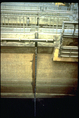 Figure 6.19: Separations in the reinforced concrete walls of the aeration tanks.
 Figure 6.12: Map of Higashinada Sewage Treatment Plant.
 Figure 6.13: Soil profile at Higashinada Sewage Treatment Plant.
 Figure 6.14: Severe lateral displacement at the inverted siphon of the plant. The pressurized pipeline siphon carried all sewage treated by the plant.
 Figure 6.15: Rupture of the main sewage treatment conduit caused by lateral spreading and settlement.
 Figure 6.16:
 Figure 6.17:
 Figure 6.18:
 Figure 6.19: