7.3 Reinforced Soil Walls
Three geogrid reinforced soils walls of the type developed by Tatsuoka et al. (1992) were visited; namely, the walls at Tanata, Amagasaki, and Tsukamoto, located as shown on Figure 7.15. Each of these walls was constructed for support of railway lines. The seismic intensities at stations close to each of these walls are shown on the figure. A comprehensive report on the performance of these walls is in preparation by Tatsuoka et al. (1995). The Tanata wall was subjected to particularly high ground accelerations; i.e., more than 0.4g in the NS direction, nearly 0.8g in the EW direction, and almost 0.4g in the vertical direction.
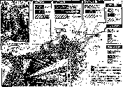 Figure 7.15: Location of Geosynthetic Reinforced Soil Walls (GRS-RW) and nearby seismic intensities (from Tatsuoka et al. 1995).
A standardized design and construction procedure for permanent geosynthetic-reinforced walls with a full-height rigid facing panels has been developed by the University of Tokyo and the Railway Technical Railway Research Institute of the Japan Railways Group. These walls are referred to as GRS-RW walls. The construction procedure follows the sequence shown in Figure 7.16 and the pseudostatic seismic design is used, assuming a horizontal inertial acceleration of 0.2g.
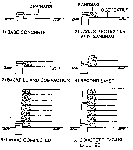 Figure 7.16: Standard construction procedure for GRS-RW wall systems (from Tatsuoka, undated).
There was no apparent damage to the walls or measurable displacements at Amagasaki or Tsukamoto, although there was some evidence that there may have been hairline cracking along the surface of the backfill at the Amagasaki wall at a distance about equal to the reinforcement length behind the face of the wall. It should be noted that in both of these areas there was little damage to other structures as well.
The Tanata wall (Figure 7.17) is located between the Ashiya and Setsu-Motoyama JR stations, near the slide shown in Figure 7.8. The wall is somewhat more than 6 m high, with PVC fiber grid reinforcements 2.5 m in length, and cohesionless backfill. A typical cross section is shown in Figure 7.18. The reinforced soil wall is founded directly on the original ground without deep foundation support. Nonetheless, the wall retained its stability, with outward deformations of about 22 cm at the top and 10 cm at the base (Figure 7.19). According to Tatsuoka et al. (1995) several reinforcement layers near the top of the wall could not be extended to the full design length owing to construction limitations, and this may have resulted in the tilting being greater that it might have been otherwise. There was settlement of all four sets of railroad tracks running along the embankment above caused by the dynamic loading; however, the track located above the reinforced backfill settled the least.
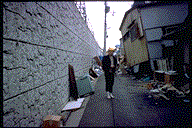 Figure 7.17: Post-earthquake view of the Tanata GRS-RW wall.
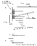 Figure 7.18: Cross-section of the GRS-RW at Tanata (from Tatsuoka et al., 1995).
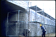 Figure 7.19: Evidence of outward rotation and displacement of the Tanata GRS-RW wall, about 20 cm at the toe and about 10 cm near the base.
Some minor spalling of the concrete facing panels was noted near the top at a construction joint, it appeared that the joint width may have opened to about 2 cm, and some hairline cracking was noted that is suggestive of longitudinal shear in the panels. However, given the extensive damage in the area (most of the buildings directly across the street from the wall had or were heavily damaged collapsed, as seen in Figure 7.17), the GRS-RW demonstrated excellent seismic resistance.
The Tanata GRS-SR wall adjoins a more conventional reinforced concrete cantilever wall which extends to the west (left) of the underpass shown in Figure 7.19. This conventional concrete wall is supported on 6 m deep, 1.2 m diameter cast-in-place reinforced concrete piers. The wall appeared outwardly undamaged, although it displaced laterally on the order of 27 cm at the top and 10 cm at the base (Figure 7.20).
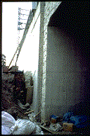 Figure 7.20: Reinforced concrete cantilever wall adjacent to the Tanata GRS-RW wall. Note the outward displacement of about 10 cm.
In addition to these walls, which were inspected on foot, two mechanically stabilized walls under construction were seen from the air on Awaji Island at the approaches to the new Akashi Kaikyo Bridge (Figure 7.21). No apparent distress was visible from the air. These walls should provide an excellent opportunity for further study, since they presumably represent the current state-of-the-art.
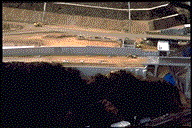 Figure 7.21: Aerial view of mechanically stabilized walls on the approach to the Awaji Island Bridge on Awaji Island.